In a PCI transaction:
-
The initiator = the device that requests a transaction.
- Example: the CPU wants to read data from memory.
- It drives the address and command onto the bus.
-
The target = the device that responds to the request.
- Example: the memory controller sees its address on the bus and responds.
- If it’s a read transaction, the target provides the data back to the initiator.
- If it’s a write transaction, the initiator provides the data, and the target just receives it.
PCI signals (like FRAME#, IRDY#, TRDY#) have a "#" at the end. That "#" means the signal is active low.
-
"Active low" → the signal is considered ON (asserted) when the voltage is 0 (low).
-
"Inactive (deasserted)" → when the signal is 1 (high).
So: -
“Initiator asserts
FRAME#” = The initiator drivesFRAME#low (0) to tell everyone that a transaction is starting. -
“Deasserts
FRAME#” = The initiator drives it high (1) to show the transaction is ending.
PCI Bus Transaction (Step by Step)
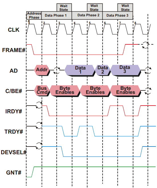
1. Clock Edge 1 – Bus Idle & Grant
FRAME#(transaction in progress) = inactiveIRDY#(initiator ready) = inactive
➡ Bus is idle.GNT#= active → arbiter has chosen this device as the next initiator.
2. Clock Edge 2 – Transaction Starts
- Initiator asserts
FRAME#→ Indicate new transaction begins. - Initiator drives address + command onto bus.
- Other devices latch this info and check if the address matches them. (To check if the request is for them)
3. Clock Edge 3 – Read Setup & Turn-Around
- Initiator asserts
IRDY#→ Indicate ready for data transfer. - AD bus goes into turn-around cycle (initiator stops driving, target will drive next then continue switching).
- This prevents bus contention (two devices driving at once).
4. Clock Edge 4 – Target Responds & First Data Transfer
-
Target asserts:
DEVSEL#→ Target recognizes the address and claims the transaction.TRDY#→ Target ready with data to send.
-
Data is driven onto the AD (Address/Data) bus.
-
Since both
IRDY#&TRDY#are active → first data transfer occurs. -
Target checks
FRAME#:- If asserted → more data requested.
- If deasserted → last transfer.
5. Clock Edge 5 – Target Wait State
- Target is not ready for next data → deasserts
TRDY#. - This inserts a Wait State (delays transfer for 1 clock).
- Both initiator and target can insert up to 8 wait cycles in a row.
6. Clock Edge 6 – Second Data Transfer
- Target ready again → second data item transferred.
FRAME#still asserted → initiator still wants more.
7. Clock Edge 7 – Initiator Wait State
- This time, initiator inserts a Wait State (e.g., buffer handling).
IRDY#deasserted - Useful for quick pauses without restarting transaction.
- Downside: inefficient, since the bus is stalled and unavailable to others.
8. Clock Edge 8 – Last Data Transfer & End
- Third data item transferred.
- Initiator deasserts
FRAME#→ signals last transfer. - After this clock → all control lines reset, bus returns to idle.
Key PCI Design Notes
-
To reduce pin count:
- Address/Data lines (AD[31:0]) are multiplexed (share same physical pins).
- C/BE# (Command/Byte Enable) lines are shared.
-
Tradeoffs:
- Requires turn-around cycles → adds delays.
- Prevents pipelining (cannot send next address while current data is transferring).
-
Control signals (
FRAME#,DEVSEL#,TRDY#,IRDY#,STOP#) manage handshakes and transaction timing.